Cabin Design Team
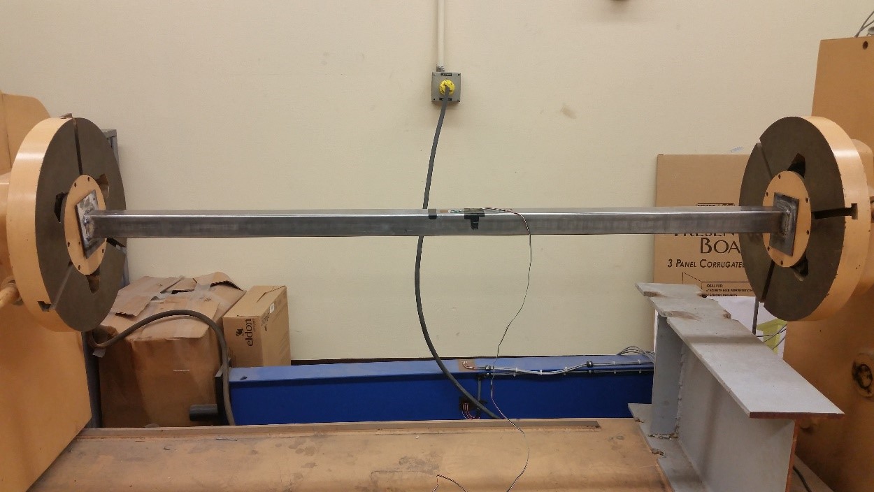
Torsion Test
Student Team Members
- Steve Trevillyan (Team Leader)
- Christopher Fong
- Ian Johnsen
- Ivan Tapia
- Kriti Kalwad (External Contact – FEA modeling)
Project Scope and Objectives
Confirm that the current railway design is capable of handling the expected loads; do an ANSYS model and confirm the model with physical tests.
- Design a torsion experiment to calibrate the torsion test machine, and note the accuracies of the machine for later analysis.
- Design a torsion experiment that results in sufficient data to confirm a finite element analysis.
- Create a model in ANSYS and compare the results to the physical test.
Project Results
- Successfully calibrated the machine using calculations for angle of twist – specimen twist found to be within an acceptable 10% error
- Successfully completed a torsion test on a hollow square pipe. The angle of twist was within 15% error.
Past Accomplishments
2013 - 2014 Cabin Team
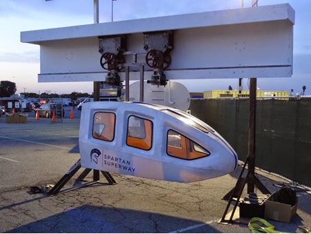
The design of the Cabin is a cross team effort between the Engineering and Industrial Design Teams. The Industrial Design Team developed various concepts of the Cabin, while the Engineering Team verifies the feasibility of the concepts. The Cabin will be suspended above the city streets with bidirectional travel capable of speeds up to 50mph. It is being designed to comfortably accommodate the travel of a maximum of 6 people, while looking esthetically pleasing. Riders will have the option to stand or sit and carry on bikes and baggage. The Cabin is currently in the conceptual design and prototype phase this semester and by the end of next semester there will be a finalized full-scale model.
2013-2014 Guideway
We began our design by examining last year's report and determining the shortcomings and successes of their work. We brainstormed ways to improve their shortcomings and ways to capitalize on their successes. Design requirements were then generated for the station and guideway sub systems. Quality Function Development was implemented in order to determine the engineering specifications from the requirements. From those specifications, we determined the major function and sub functions of the systems. A document was prepared regarding the stations requirements, specifications, and functions to give the Industrial Design students specific guidance as to their designs for the following semester.
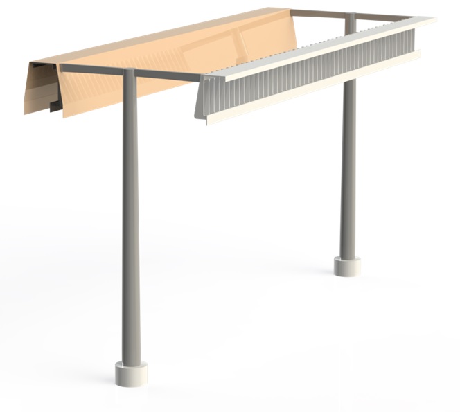
The guideway design then became the primary focus of our team. We began generating concepts for cross sectional geometry, support structure geometry, and switching mechanism implementations. We decided on an I-beam shaped cross section with guidance rails on the underside of the beams. For the remainder of the project we will be conducting mathematical analyses on the guideway system and engineering the design for the guideway, support, and switches. We will then use our design to build a full-scale model of the system.
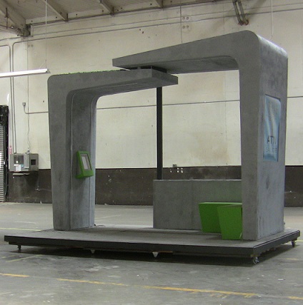
2013-2014 Station Design Team
We began our design by examining last year's report and determining the shortcomings and successes of their work. We brainstormed ways to improve their shortcomings and ways to capitalize on their successes. Design requirements were then generated for the station and guideway sub systems. Quality Function Development was implemented in order to determine the engineering specifications from the requirements. From those specifications, we determined the major function and sub functions of the systems. A document was prepared regarding the stations requirements, specifications, and functions to give the Industrial Design students specific guidance as to their designs for the following semester.
The guideway design then became the primary focus of our team. We began generating concepts for cross sectional geometry, support structure geometry, and switching mechanism implementations. We decided on an I-beam shaped cross section with guidance rails on the underside of the beams. For the remainder of the project we will be conducting mathematical analyses on the guideway system and engineering the design for the guideway, support, and switches. We will then use our design to build a full-scale model of the system.
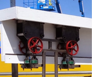
2013-2014 Bogie Team
The Bogie Team, part of the Spartan Superway project, is challenged with providing the structural support, propulsion, and guideway navigation of the personal rapid transit vehicle. The developments made by the team have been closely linked with changes to the guideway design. The Bogie Team is responsible for everything between the guideway and the roof of the cabin.
 The next development came from an oddity in the cross section: the flat running boards
for the wheels to roll on. Wouldn't it be cheaper to simply roll a flat piece of steel
and be done with it? Thus the tubular design was born. This design featured wheels
which had strong negative camber, allowing them to ride perpendicular to the tangent
of the inner surface of the guideway. This causes a centering effect, and also enables
the bogie-cabin system to be rigid. Instead of there being a hinleftge to allow swinging
during cornering, the whole bogie could rotate in the guideway. To maximize traction
and stability, the drive wheels would be driven along the top of the guideway, with
traction force provided by a hydraulic system.
The next development came from an oddity in the cross section: the flat running boards
for the wheels to roll on. Wouldn't it be cheaper to simply roll a flat piece of steel
and be done with it? Thus the tubular design was born. This design featured wheels
which had strong negative camber, allowing them to ride perpendicular to the tangent
of the inner surface of the guideway. This causes a centering effect, and also enables
the bogie-cabin system to be rigid. Instead of there being a hinleftge to allow swinging
during cornering, the whole bogie could rotate in the guideway. To maximize traction
and stability, the drive wheels would be driven along the top of the guideway, with
traction force provided by a hydraulic system.
Currently, the guideway design has changed to be an I-beam design, wherein the bogie is no longer enclosed in the guideway. A suitable design for this guideway shape is in progress. The hydraulic system will likely be maintained to allow the drive wheels to clamp the bogie down onto the track. A possibility which was considered with the previous designs was use of a linear induction motor, but the benefits didn't outweigh the costs. With this new, more compact bogie design, however, the benefits of LIM's are more prominent, and the Bogie team is interested in employing these devices. Unfortunately, there are few resources to help us compare the costs, efficiencies, and operations of linear drive systems with conventional methods, and we are seeking assistance from anyone with experience in linear motor propulsion.
Despite its silly name, the bogie is an incredibly complex and important piece of the vehicle, and challenges are presenting themselves daily, but we are excited to design an implement this critical component and its systems!
During the initial weeks of the project, the guideway design was changed to be a circular cross section in order to reduce stress concentrations and buckling problems which would occur in the square-tube design demonstrated by the 12th scale model. The first development aimed at stabilizing the ride of the bogie and reducing the turning radius was the split-bogie design, which involved two bogies which could rotate independently of one another, and which only had 2 support wheels each, eliminating wheel slip during cornering. This design was rejected because of the possibility for a bogie to become twisted in the track.